

- All
- Product Name
- Product Keyword
- Product Model
- Product Summary
- Product Description
- Multi Field Search
Views: 0 Author: Site Editor Publish Time: 2026-10-20 Origin: Site


Lightning strikes frequently trigger catastrophic power grid failures. Specify incorrect protective ratings, and expensive transformers are left completely vulnerable. This engineering oversight inevitably leads to costly, preventable outages that frustrate consumers and damage utility reputations. By understanding exactly when and how to implement proper overvoltage protection, grid operators can effectively safeguard their most critical infrastructure.
Recent industry analyses reveal a massive shift in grid modernization strategies. Extreme weather events are driving up regional isokeraunic, or lightning activity, levels globally. Consequently, utility operators are rapidly abandoning reactive maintenance. The current engineering consensus focuses heavily on preemptive grid hardening. Modern distribution networks demand gapless metal-oxide varistor technology housed in advanced polymers. These modern materials offer superior energy absorption and pollution resistance, ensuring aging grids survive unpredictable transient surges associated with severe climate challenges.
In this comprehensive technical guide, we detail exactly when to specify a 10-34kV Surge Arrester for Distribution. We will explore technical specifications, real-world application scenarios, and the critical criteria necessary for making an informed, reliable procurement decision.
Essential Protection: Devices rated between 10kV and 34kV are mandatory for defending medium-voltage distribution transformers, underground cables, and overhead lines against volatile lightning and switching surges.
Voltage Sizing is Critical: Proper selection relies heavily on evaluating the system Maximum Continuous Operating Voltage and identifying whether the network is solidly grounded, impedance-grounded, or ungrounded.
Material Advancements: Polymer, specifically silicone rubber, housings have largely replaced legacy porcelain. They provide superior hydrophobic properties, lighter handling weight, and shatter-proof safety profiles.
Application-Specific Selection: Differentiating between normal-duty, heavy-duty, and specialized riser-pole units is necessary to match the unique energy-handling requirements of specific installation environments.
Standard Compliance: Sourcing from manufacturers that strictly adhere to IEC 60099-4 and IEEE C62.11 standards guarantees reliable, long-term performance and overall grid stability.
Medium-voltage distribution networks form the critical backbone of global power delivery. They effectively bridge the massive gap between high-voltage transmission substations and the low-voltage endpoints that power homes and businesses. Because these extensive overhead networks are highly exposed to the elements, they remain exceptionally susceptible to transient overvoltages.
At its core, a surge arrester is a primary protective device installed across power systems. Its job is to instantly limit overvoltages and safely divert excess surge current directly into the ground. Modern devices engineered for the 10 to 34 kilovolt range utilize highly advanced Metal Oxide Varistor technology. The internal structure consists of stacked zinc oxide blocks, which exhibit remarkably nonlinear voltage-current characteristics.
Under normal operating conditions, the varistor acts as a robust insulator. It permits only a negligible leakage current, typically measured in microamperes, to flow through. However, the moment a transient overvoltage hits the line, the internal blocks instantly transition into a highly conductive state. The device forcefully clamps the voltage to a safe level, absorbs the immense thermal energy, and channels it to the earth. Once the surge passes, the unit seamlessly reverts to its insulating state. This rapid action prevents the overvoltage from breaching the delicate insulation of downstream equipment.
This specific voltage classification perfectly aligns with standard utility distribution voltages utilized across the globe. Common nominal system voltages falling within this tier include 11kV, 15kV, 24kV, 33kV, and 34.5kV. Unlike massive high-voltage station-class units designed for substations, the distribution class strikes a necessary operational balance. It provides robust energy absorption capacity while remaining cost-effective enough for widespread deployment across thousands of utility poles.
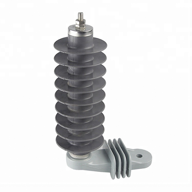
Selecting the correct surge protection is never a generalized process. It demands a rigorous engineering assessment of specific grid vulnerabilities. Deciding to deploy a 10-34kV Surge Arrester for Distribution becomes an absolute necessity in several critical operational scenarios.
Distribution transformers represent some of the most expensive and vital assets mounted on any overhead line. Their internal paper and oil insulation systems possess a highly specific Basic Insulation Level. If a transient surge exceeds this threshold, the transformer windings will suffer immediate dielectric breakdown. In practical terms, this results in catastrophic equipment failure, hazardous boiling oil leaks, and extended power outages.
To prevent this, a dedicated protective device is required at every single transformer installation. Linemen typically mount these units as close to the transformer bushings as physically possible. This close-proximity installation minimizes the inductive voltage drop across the connecting leads. It ensures the incoming surge voltage is clamped well below the transformer insulation limits, keeping the asset operational even through severe electrical storms.
Furthermore, one of the most technically demanding application scenarios occurs at transition points. These are commonly referred to as riser poles or dip poles, where overhead lines splice into underground cables. When a high-speed traveling voltage wave moves from an overhead line into a buried cable, a significant portion of that wave is reflected due to surge impedance differences.
Consequently, when this surge reaches the open point at the far end of the underground cable, the voltage can effectively double. To mitigate this severe wave reflection threat, specialized riser-pole arresters possessing lower discharge voltages and substantially higher energy-handling capabilities must be installed right at the transition point. This ensures the highly vulnerable extruded cable insulation is not compromised.
Utilities operating in regions with high thunderstorm days per year simply cannot rely on standard-duty protection. In such volatile environments, engineers must actively specify heavy-duty models. Heavy-duty units feature physically larger varistor blocks capable of dissipating massive amounts of thermal energy. Upgrading your network protection in these active zones is a mathematically proven strategy to slash ongoing replacement costs and drastically improve system reliability indices.
Procurement managers and grid engineers must carefully evaluate specific technical parameters to guarantee the selected protective device functions safely within their unique network topology. Overlooking these metrics inevitably leads to rapid hardware degradation.
The Maximum Continuous Operating Voltage stands as the absolute most critical specification during the selection process. It represents the maximum root-mean-square power-frequency voltage that can be continuously applied to the device terminals without triggering thermal degradation. If an engineer chooses a rating that is too low, the varistor blocks will begin conducting during normal everyday operating conditions. This continuous conduction leads to rapid thermal runaway and an explosive failure.
In contrast, selecting a rating that is excessively high results in a higher clamping voltage, which dangerously reduces the protective margin for the connected equipment. The golden rule is that the continuous operating voltage must always remain slightly greater than the maximum phase-to-ground voltage of the system under normal conditions.
Distribution networks routinely experience Temporary Overvoltages triggered by single line-to-ground faults or sudden load rejections. A high-quality device must feature a clearly defined withstand capability, dictating exactly how long it can endure these elevated power-frequency voltages before suffering permanent damage. System protection engineers must meticulously match this withstand curve with the utility relay clearing times.
Specifically, the nominal discharge current classifies the inherent ability to handle massive lightning surge currents. For standard medium-voltage distribution networks, these units are typically rated at either 5kA or 10kA. To clarify the application differences, review the standard engineering comparison below.
Specification Feature | 5kA Normal Duty Arrester | 10kA Heavy Duty Arrester |
|---|---|---|
Typical Application | Rural grids, low lightning activity zones | Commercial feeders, high isokeraunic zones |
Energy Absorption Capacity | Moderate thermal dissipation | High thermal dissipation, multiple strike survival |
Fault Current Withstand | Suitable for lower system fault currents | Engineered for high short-circuit environments |
Riser Pole Suitability | Not recommended | Mandatory for overhead-to-underground transitions |
The external housing serves as the primary defense for the internal blocks, shielding them from environmental degradation, moisture ingress, and mechanical stress. While porcelain was historically the default standard, modern distribution networks have almost entirely transitioned to advanced polymer housings.
Polymer-housed units utilizing high-grade silicone rubber offer overwhelming operational advantages. First and foremost is their inherent hydrophobicity. Silicone rubber naturally repels water. Even when installed in heavily polluted coastal salt fog zones, water simply beads up on the surface rather than forming a continuous conductive film. This unique trait actively prevents surface tracking and dry-band arcing.
Furthermore, polymer housings provide a shatter-proof safety profile. If a legacy porcelain unit fails catastrophically due to an internal short circuit, the immense pressure buildup causes the rigid ceramic to explode, launching dangerous shrapnel. Polymer models are engineered to tear open and vent pressure safely, entirely eliminating the shrapnel risk to nearby linemen. From a practical installation standpoint, polymer units weigh significantly less, drastically reducing mechanical stress on wooden crossarms.
Selecting the exact specifications for your network requires a highly methodical calculation process. Engineers should follow these standardized steps to ensure optimal protection margins and maximize asset longevity.
First, determine the system grounding configuration. The neutral grounding topology directly dictates the severity of the overvoltages the device will experience during a fault. In solidly grounded systems, a line-to-ground fault causes minimal voltage rise on the unfaulted phases. Conversely, in ungrounded systems, a fault on one phase forces the voltage on the remaining healthy phases to rise to the full phase-to-phase voltage. Equipment installed in these specific networks must possess a significantly higher continuous operating voltage.
Second, calculate the precise voltage requirement. For a standard three-phase system, identify the maximum system voltage, calculate the maximum phase-to-ground voltage, and apply the appropriate earth fault factor. Ensure the chosen device can comfortably exceed this calculated fault voltage for the entire duration of the relay clearing time.
Third, assess environmental and creepage requirements. The physical installation environment dictates the required creepage distance, which is the shortest path along the surface of the insulator between the high-voltage terminal and the grounded bracket. While standard creepage distances are perfectly sufficient for rural areas, highly polluted environments demand more. Coastal areas battling salt spray require high-creepage models to prevent surface flashovers.
Procurement errors in surge protection often introduce hidden, dormant vulnerabilities into the distribution network. Avoiding these common technical oversights when specifying a 10-34kV Surge Arrester for Distribution will save utilities significant replacement capital and prevent unplanned blackouts.
A remarkably frequent misconception among junior engineers is that selecting a voltage rating higher than necessary provides an extra buffer of safety. In reality, over-sizing severely compromises equipment protection. The primary function of this device is to clamp transient overvoltages below the insulation limits of the transformer. If the rating is too high, the discharge clamping voltage will also be higher, which drastically shrinks the protective margin. A lightning surge will likely destroy the transformer paper insulation before the varistor blocks can fully divert the energy.
Additionally, ignoring the fault current pressure relief rating is a critical error. When a device absorbs thermal energy beyond its physical design limits, the internal blocks will fail and create a short circuit. This causes internal gases to expand instantly. If the unit is not specified with an adequate pressure relief rating, the housing cannot vent fast enough and will explode. Buyers must meticulously verify that the short-circuit rating meets or exceeds the maximum available fault current at that specific installation node.
Calculating the correct electrical specifications is only half the battle. Selecting a reliable manufacturing partner is equally critical. The manufacturing integrity of the internal blocks and the precision of the silicone sealing mechanism ultimately determine whether the unit will survive five years or thrive for two decades in the field.
Technical buyers and procurement teams should exclusively source devices from manufacturers that strictly adhere to international testing standards, primarily IEC 60099-4 or IEEE C62.11. Before finalizing any bulk purchase, insist on reviewing certified type test reports. These documents provide empirical evidence that the design has successfully passed rigorous operating duty cycle tests, short-circuit pressure relief tests, and accelerated weather aging protocols.
For utility companies and electrical contractors seeking verified, long-term reliability, partnering with established manufacturers ensures true grid stability. High-quality production lines utilize advanced powder formulations and void-free silicone injection molding techniques to completely eliminate moisture ingress, which remains the leading cause of premature failure in the field.
When specifying components for critical infrastructure, engineers must select devices explicitly engineered for longevity and precise voltage clamping. Explore high-performance options and find the exact specifications for your infrastructure by visiting Long Insulator. Their comprehensive range of 10-34kV Surge Arrester for Distribution products ensures your transformers and underground cables remain fully protected against unpredictable transient surges for decades to come.
Under normal operating conditions, a well-manufactured unit typically lasts between 15 to 20 years. However, this lifespan is heavily dependent on the frequency and severity of lightning strikes it absorbs, the number of switching surges it handles, and local environmental factors. Continuous exposure to extreme UV radiation or heavy coastal salt pollution can accelerate the degradation of the external housing and the internal varistor blocks.
No, this is a highly dangerous engineering practice. While the device will easily survive normal daily operations, over-sizing the voltage rating means its discharge clamping voltage will be far too high. It will not trigger at the correct overvoltage threshold, effectively leaving your 15kV transformers and delicate underground cables completely unprotected against rapid lightning surges. Always size the continuous voltage rating closely to the actual operating voltage of the system.
The primary difference lies in their respective energy-handling capabilities and physical dimensions. Distribution class models are engineered to handle moderate energy surges and are typically installed on standard medium-voltage wooden poles, overhead lines, and transformers. Station class models are significantly larger, built with massive internal blocks designed to safely dissipate extreme energy surges, and are utilized exclusively to protect highly expensive, critical equipment inside large electrical substations.
Utility maintenance teams should conduct visual inspections at least annually. Linemen should look for deployed ground lead disconnectors, which act as a clear visual indicator that the unit has failed and safely disconnected itself from the ground. Crews should also check for cracks in the housing or severe pollution buildup. Additionally, utilizing thermal imaging cameras or performing leakage current testing every three to five years is highly recommended to detect internal degradation long before a catastrophic fault occurs.
A lightning rod is a structural protection device designed to intercept direct lightning strikes and channel the current safely to the ground to prevent physical fire or structural damage to buildings. A surge arrester is an electrical protection device connected directly to power lines. It does not attract lightning; instead, it intercepts extreme voltage spikes traveling through the electrical wires, clamping the voltage to protect sensitive downstream equipment like transformers from dielectric insulation breakdown.
When a modern polymer unit absorbs a surge exceeding its thermal capacity, the internal metal-oxide blocks permanently short-circuit. To prevent a continuous line-to-ground fault that would lock out the entire feeder, a ground lead disconnector attached to the bottom bracket safely detonates. This small explosive charge drops the ground wire, isolating the failed unit from the earth and allowing the power line to remain energized until maintenance crews can replace the sacrificed device.


