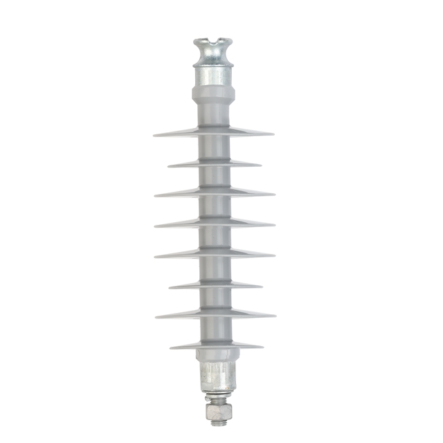
Coastal environments present some of the most brutal operational challenges for electrical distribution grids. Picture a utility pole standing just a few miles from the shoreline. It gets battered by offshore gales and soaked in saline moisture day after day. Standard grid hardware simply cannot survive here. Relentless salt fog, hurricane-force winds, and sustained high humidity constantly attack the infrastructure. Eventually, this degradation causes catastrophic line drops and costly power outages. Utility operators are then left footing a massive maintenance bill.
While electrical flashovers are a well-documented issue, mechanical failure driven by high dynamic wind loads remains a primary operational concern that engineers must proactively address. The modern polymer grid component offers a highly effective solution for these harsh environments, provided it is engineered to meet precise mechanical load ratings. Balancing electrical hydrophobicity with structural rigidity is the critical key to long-term grid stability. This comprehensive technical guide will break down the exact load ratings, testing standards, and engineering selection criteria required for coastal applications, offering specific insights into specifying a reliable 33kV composite pin insulator in high-wind zones.
Key Takeaways
Cantilever Strength is Crucial: In coastal areas, high wind speeds dictate that the Specified Cantilever Load and Maximum Design Cantilever Load are the most critical mechanical metrics for grid safety.
Environmental Synergy: Mechanical load capacity cannot function in isolation. It must be paired seamlessly with superior tracking and erosion resistance to survive continuous salt spray without core degradation.
33kV Specifics: Medium-voltage distribution lines in a coastal grid typically require a minimum cantilever strength ranging between 5kN and 10kN, heavily dependent on the conductor span and regional wind velocity zones.
Composite vs. Porcelain: Polymer materials offer a significantly higher strength-to-weight ratio and crucial material flexibility, making them structurally superior for absorbing dynamic wind loads compared to rigid ceramics.
Industry Trends: The Push for Climate-Resilient Grid Modernization
Recent data from coastal utility operators reveals a massive shift in procurement strategies. As global weather patterns shift, the frequency and intensity of coastal storms have spiked significantly. Consequently, grid modernization initiatives are no longer just about smart meters; they are heavily focused on physical climate resilience. Industry analysts note a rapid phase-out of legacy ceramic infrastructure in favor of advanced polymer technologies. Utilities are now mandating higher mechanical safety margins to future-proof their networks against extreme dynamic loads. Planners recognize that upfront investments in high-strength, weather-resistant materials drastically reduce long-term outage penalties and maintenance overhead.
Why Coastal Environments Demand Strict Load Ratings for Insulators
Standard operational parameters fall short when designing power networks near the ocean. The unique environmental context of a coastal zone requires engineers to completely rethink mechanical stress tolerances. Driven by the increasing frequency of severe coastal storms, grid modernization initiatives now heavily favor technologies that can withstand extreme dynamic loads while maintaining electrical integrity.
High Wind Speeds and Hurricane Forces
Coastal topographies are inherently exposed to constant offshore winds and violent seasonal typhoons. The kinetic energy generated by these weather events transfers directly from the heavy power conductors to the supporting hardware. Imagine a medium-voltage distribution line during a storm. The thick aluminum conductors act like massive sails, catching the wind and transferring immense horizontal force directly to the insulator head.
Furthermore, two specific aerodynamic phenomena put immense dynamic mechanical stress on the unit. First is aeolian vibration, which consists of high-frequency oscillations caused by steady winds passing across the conductor. Over time, this constant buzzing can cause microscopic fatigue in the mounting hardware. The second is conductor galloping, a low-frequency movement often exacerbated by turbulent storm conditions. Galloping creates violent bending moments. If the dielectric component lacks the proper cantilever strength, the internal fiberglass core will fracture, leading to immediate line drops.
The Impact of Salt Fog and Corrosion on Mechanical Integrity
While airborne saline moisture is primarily viewed as an electrical hazard that causes surface tracking, its impact on structural integrity is equally destructive. Salt accumulation combined with high humidity creates a highly corrosive micro-environment for the metal end-fittings.
The most vulnerable area is the crimping zone, which is the precise location where the Fiberglass Reinforced Polymer core meets the galvanized steel fitting. If salt-induced galvanic corrosion compromises this metal fitting, the mechanical grip on the fiberglass core weakens significantly. From a structural standpoint, the sealing in this zone must be flawless. Under heavy wind loads, the assembly flexes. Should the seal break during this flexion, moisture and acid will ingress into the core. This leads to brittle fracture, a catastrophic failure mode where the internal rods are essentially eaten away from the inside out.
Core Mechanical Load Ratings a Composite Pin Insulator Must Meet
To ensure grid reliability, procurement managers and engineers must scrutinize specific technical metrics on a manufacturer datasheet. Relying on guesswork is not an option. Understanding the exact definitions and practical applications of these load ratings is non-negotiable for coastal deployment.
Specified Cantilever Load
The Specified Cantilever Load represents the ultimate mechanical threshold of the insulator. It defines the maximum lateral force the unit can withstand before structural failure occurs. In typical pin-type applications, the hardware is mounted vertically on crossarms, acting as a cantilever beam fixed at its base.
In coastal applications, a robust rating is mandatory. When gale-force winds push against the attached power lines, the insulator experiences immense leverage at its base. This ultimate rating ensures that the diameter and structural quality of the internal core are sufficient to resist this ultimate bending force without snapping. Engineers calculate the required load by factoring in local historical peak wind velocities, conductor diameter, and the length of the span between utility poles.
Maximum Design Cantilever Load
While the ultimate load indicates the absolute breaking point, the Maximum Design Cantilever Load dictates the safe, continuous operational limit. By international engineering standards, this design load is strictly defined as 50 percent of the ultimate breaking strength.
An insulator must operate safely at or below this design limit during its daily lifespan. This safety margin is critical in coastal zones. It accounts for unpredictable micro-bursts of wind, gradual material fatigue over a two-decade service life, and potential added weight from ice loads during winter storms in northern coastal regions. Consistently operating above this design limit will cause mechanical creep, leading to slow, permanent deformation of the fiberglass core and eventual premature failure.
Tensile and Torsional Loads
Though cantilever strength dominates the conversation for pin-type components, tensile and torsional loads must also be thoroughly evaluated. Tensile load refers to the downward vertical pull exerted by the dead weight of the conductor and any accumulated ice. Torsional load refers to twisting forces, which can occur during conductor binding or if a line breaks on one side of the pole, causing the wire to torque the head. High-quality coastal hardware features forged steel pins and robust, acoustically monitored crimping to resist these secondary rotational stresses without compromising the weather seal.
Deep Dive: Load Requirements for a 33kV Composite Pin Insulator
Medium-voltage distribution networks form the backbone of power delivery in many coastal municipalities. Scaling up from 11kV to 33kV introduces new mechanical and electrical challenges that dictate significantly stricter specifications.
Matching Load Ratings to 33kV Conductors
Upgrading to a 33kV infrastructure inherently means utilizing heavier, thicker conductors to carry higher capacities over longer spans. This increased physical mass directly translates to higher mechanical tension. Specifically, a larger conductor diameter creates a broader surface area for the wind to catch, drastically increasing the lateral aerodynamic force transferred to the mounting hardware.
Consequently, standard 33kV composite pin insulators designed for coastal deployment must possess substantial mechanical strength. While a lighter 11kV line might survive with a 5kN ultimate load, a 33kV installation in a high-wind coastal zone typically requires a benchmark cantilever strength of at least 10kN. In areas prone to extreme cyclones, utility planners frequently specify 12.5kN to maintain an impenetrable safety margin.
Creepage Distance vs. Mechanical Strength
In coastal environments, high voltage requires aggressive electrical insulation. A 33kV line demands extra-heavy creepage distances, often exceeding 31mm per kV, to prevent salt-induced surface flashovers. To achieve this extended creepage, manufacturers design products with larger, wider silicone rubber sheds.
However, larger sheds increase the aerodynamic drag of the insulator itself, meaning it catches more wind. This creates a direct engineering conflict between electrical design and mechanical stability. To resolve this paradox, the internal core of a coastal 33kV unit must be engineered with a thicker diameter to support the increased wind resistance caused by the larger silicone profile, ensuring the mechanical strength remains uncompromised.
Porcelain vs. Composite Pin Insulators in High-Load Coastal Scenarios
For decades, porcelain was the default material for utility grids. Yet, empirical field performance data has proven that polymer materials offer distinct mechanical advantages when subjected to the harsh, dynamic loads of coastal environments.
Flexibility and Dynamic Load Absorption
Traditional porcelain is a ceramic. It is highly rigid, brittle, and possesses zero elasticity. When a sudden, violent gust of coastal wind hits a porcelain-supported line, the material cannot flex. It must absorb the shock entirely through its static density. If the kinetic force exceeds its limit, it shatters instantly, dropping the live wire.
Conversely, a polymer unit relies on its internal fiberglass core. This core possesses a calculated degree of flexibility. When subjected to the dynamic loads of conductor galloping or aeolian vibrations, the insulator can bend but not break. This inherent elasticity allows it to absorb and safely dissipate kinetic energy, significantly reducing the risk of catastrophic mechanical failure during hurricane-force winds.
Tower Stress and Weight Reduction
Coastal winds do not just stress the insulators; they exert immense pressure on the entire utility pole and crossarm infrastructure. Polymer alternatives offer a massive advantage in weight reduction, often weighing up to 70 percent less than their porcelain counterparts.
By replacing heavy ceramics with lightweight composite units, utilities drastically reduce the static dead-weight load on the crossarms. Lowering this top-heavy mass reduces the overall mechanical stress on the tower, freeing up structural capacity to handle the dynamic horizontal forces introduced by coastal storms. In practical terms, this weight advantage also makes installation safer and faster for line crews working in difficult, muddy coastal terrains.
Essential Testing Standards for Coastal Composite Pin Insulators
Procurement decisions for critical grid components cannot rely on marketing claims alone. They must be validated through rigorous, standardized laboratory testing. Adhering to global standards ensures the hardware will perform reliably under specified mechanical loads.
IEC 61952 and ANSI C29.13 Standards
The international benchmarks governing the mechanical and electrical testing of these components are IEC 61952 and ANSI C29.13. These standards outline strict protocols for verifying mechanical integrity, most notably the cantilever breaking load test.
During this procedure, the unit is mounted to a rigid base simulating a crossarm. A mechanical ram applies a lateral force perpendicular to the core at the wire groove, steadily increasing the pressure until failure occurs. To pass the standard, the actual breaking load must meet or exceed the manufacturer declared ultimate load. Verifying IEC compliance guarantees the unit can withstand predicted peak wind pressures.
Long-Term Mechanical Load Tests
Because coastal winds can persist for days during storm systems, short-term breaking tests do not tell the whole story. To simulate real-world endurance, standards require long-term mechanical load tests, frequently referred to as the 96-hour test.
In this evaluation, the hardware is subjected to a continuous mechanical load for 96 consecutive hours at ambient temperature. Afterward, engineers meticulously inspect the unit for permanent deformation of the fiberglass and core-fitting separation. If the crimping zone shifts or the core micro-fractures during this sustained stress, the unit fails. Passing this rigorous test is vital for coastal deployment.
Expert Tips for Choosing the Right Composite Pin Insulator for Coastal Areas
Selecting the correct hardware requires balancing mechanical data with environmental realities. Utility planners should adhere to specific empirical guidelines when specifying components for coastal grids.
Calculate Local Wind Spans Accurately Never rely on generic load ratings or average estimates. Always calculate the maximum wind span, conductor tension, and historical peak wind velocities of your specific coastal topography before selecting a mechanical rating. Over-engineering by 20 percent is a standard, highly recommended safety practice in hurricane-prone zones.
Demand High-Quality End Fittings Mechanical strength is irrelevant if the metal rusts away. Ensure that all metal end-fittings and pins are manufactured from high-grade forged steel and treated with heavy-duty hot-dip galvanization according to ISO 1461 standards. This provides a thick, sacrificial zinc barrier against coastal salt corrosion.
Verify the Crimping Technology The junction between the metal fitting and the fiberglass core is the weakest link in the assembly. Ensure the manufacturer utilizes acoustic emission testing during the crimping process. This advanced monitoring detects microscopic acoustic waves caused by fiberglass fracturing, guaranteeing that the crimp is tight enough to hold the load, but not so tight that it crushes the core.
Check for UV and Salt Resistance If the silicone housing degrades, the internal core is exposed to moisture and eventual mechanical failure. Specify hardware manufactured with premium High-Temperature Vulcanized silicone rubber. This premium silicone maintains its water-repelling properties even under intense coastal UV radiation and relentless salt fog accumulation.
Request Certified Type Test Reports Never finalize a procurement order without reviewing independent, third-party laboratory test reports. These documents must explicitly prove that the specific model has passed the cantilever breaking tests and long-term mechanical load tests outlined by IEC or ANSI standards.
Where to Source Reliable Composite Pin Insulators for Coastal Projects
Securing a power grid against coastal storms requires partnering with a manufacturer that deeply understands the complex synergy between harsh weather degradation and mechanical engineering. Off-the-shelf, generic solutions frequently fail to meet the rigorous demands of high-salinity, high-wind environments, leading to unacceptable maintenance costs.
Utility planners must seek out suppliers with a proven track record in manufacturing high-strength, weather-resistant infrastructure. Facilities that utilize automated crimping technologies, strict acoustic emission monitoring, and premium silicone are essential for producing reliable coastal hardware. For engineers looking to secure their distribution networks, exploring verified options like a heavy-duty 33kV composite pin insulator designed specifically to meet stringent mechanical requirements is the most effective way to ensure long-term stability.
Conclusion
Coastal areas are unforgiving environments that rapidly expose the weaknesses in standard utility hardware. Choosing the right insulator is a meticulous balancing act between providing robust electrical insulation against salt fog and ensuring rugged mechanical load ratings to combat relentless wind forces. Upgrading your grid requires strict adherence to safety standards and an uncompromising approach to quality.
Whether you are retrofitting an aging 11kV line or installing a reliable 33kV composite pin insulator, adhering to maximum design parameters and IEC testing protocols is non-negotiable for grid safety. Always consult with trusted manufacturers to calculate the exact load requirements tailored to your specific coastal topography, ensuring your infrastructure stands strong against the elements for decades to come.
FAQ
What is the minimum cantilever load rating for a coastal composite pin insulator?
While it varies based on conductor size and span, a minimum of 5kN is standard for lighter lines. However, coastal areas subject to high winds and storms often require ratings of 10kN to 12.5kN to ensure a safe operational margin during extreme weather events.
Can a 33kV composite pin insulator withstand hurricane-force winds?
Yes, provided it is specified correctly. A high-quality polymer unit featuring a robust fiberglass core and proper acoustically monitored crimping can withstand extreme dynamic wind loads significantly better than traditional porcelain, largely due to its inherent material flexibility and ability to absorb kinetic shock.
How does salt fog affect the mechanical strength of an insulator?
Salt fog does not degrade the internal fiberglass core directly, but it causes severe galvanic corrosion on the metal end-fittings. If these fittings rust, the mechanical connection to the core weakens, which can lead to moisture ingress, brittle fracture, and line drops under heavy wind loads.
What is the difference between ultimate strength and design load?
The ultimate strength is the absolute breaking point of the insulator, meaning the maximum force it can take before snapping. The design load is the safe, continuous operating limit for everyday use. By international engineering standards, this safe limit is strictly set at 50 percent of the ultimate breaking strength for safety and longevity.
Why are composite pin insulators preferred over porcelain in coastal areas?
Beyond their superior water-repelling properties, which effectively prevent salt-induced flashovers, composite insulators are up to 70 percent lighter, drastically reducing static pole stress. Furthermore, they feature a flexible core that absorbs the vibrations and dynamic mechanical shocks caused by high coastal winds, whereas rigid porcelain tends to shatter under sudden impact.