Modern power grids face unprecedented stress from extreme weather events and airborne contaminants. High-voltage transmission networks demand components balancing mechanical endurance and superior pollution performance. This operational reality quickly shifts industry preference away from traditional porcelain strings.
A well-designed Composite Long Rod Insulator offers significant weight reduction and excellent surface hydrophobicity. However, improper specification can lead to catastrophic grid failures. We frequently see brittle fracture or severe flashovers when buyers ignore vital environmental contexts. To procure reliably, utility engineers and procurement teams must deeply evaluate core materials, sealing technologies, and environmental compliance frameworks. You simply cannot rely solely on standard catalog specifications.
We will explore the critical technical parameters and field-tested strategies needed to specify the exact right insulator for your network. You will learn how to decode load ratings, assess material purity, and avoid common procurement traps.
Key Takeaways
Assess the "Triple Point": The most critical failure zone is the junction between the fiberglass core, silicone housing, and metal end-fitting; insist on verified sealing technologies.
Match Creepage to Environment: Pollution severity dictates shed design—standard profiles fail in coastal or heavy industrial zones.
Demand Type Testing: Shortlist only manufacturers providing transparent, third-party IEC 61109 or ANSI C29.11 test reports.
1. Defining Baseline Application Requirements
Successful insulator selection begins long before reviewing manufacturer brochures. You must accurately define the exact physical and electrical stresses your transmission line will experience. Overlooking baseline requirements often guarantees premature component failure.
System Voltage & Clearances
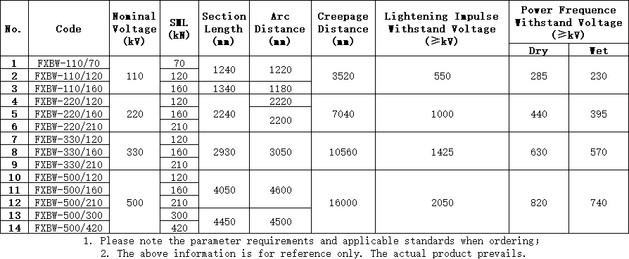
You must carefully align the insulator length and arcing distance to your network's operational voltage. Common transmission voltages include 110kV, 220kV, and 400kV. Beyond continuous operating voltage, the unit must withstand sudden transients. Switching impulse and lightning impulse voltages dictate the required dry arcing distance. If you undersize this parameter, you risk frequent electrical arcs jumping across the hardware during storms or grid switching events.
Mechanical Load (SML & RTL)
Composite insulators hold the physical weight of transmission lines while resisting dynamic weather forces. You must calculate two fundamental mechanical ratings. First, determine the Specified Mechanical Load (SML). This represents the ultimate breaking strength. Second, establish the Routine Test Load (RTL), typically 50% of the SML. Manufacturers use the RTL to test every unit before shipping.
To accurately calculate these loads, follow these sequential steps:
Calculate the total weight of the conductor across the maximum span length.
Add projected ice loading based on historical regional weather data.
Factor in maximum transverse wind forces pressing against the conductor and insulator profile.
Apply your utility’s required safety margin multiplier to determine the final SML.
Environmental Pollution Mapping
Airborne pollutants act as conductive pathways across the insulator surface. You must utilize Site Pollution Severity (SPS) data to determine the necessary specific creepage distance. Creepage is the shortest path along the insulator surface between the two metal end-fittings. Coastal areas require alternating shed profiles to prevent salt spray bridging. Heavy industrial zones demand extended creepage distances to counter metallic dust accumulation.
2. Technical Evaluation: Anatomy of a Polymer Long Rod Insulator
Not all composite materials offer equal performance. Peeling back the layers of a Polymer Long Rod Insulator reveals distinct engineering choices. Each component plays a specific role in ensuring longevity.
The FRP Core Rod
The core rod provides the essential mechanical backbone. It consists of Fiberglass Reinforced Plastic (FRP). You must actively differentiate between standard E-glass and ECR glass. Electrical discharges combined with moisture create nitric acid on the insulator surface. If this acid reaches a standard E-glass core, it leaches boron from the glass. This chemical attack causes sudden mechanical snapping, known as brittle fracture.
Actionable check: Always specify boron-free ECR cores to eliminate susceptibility to nitric acid attack. Below is a quick comparison chart illustrating why ECR is mandatory.
Chart: Standard E-Glass vs. ECR Glass Cores
Feature
Standard E-Glass
ECR Glass
Boron Content
High
Zero (Boron-Free)
Acid Resistance
Poor
Excellent
Brittle Fracture Risk
High
Eliminated
Application Suitability
Low-stress environments
High-voltage transmission lines
Housing and Shed Material
The external housing protects the core from environmental degradation. You should evaluate High-Temperature Vulcanized (HTV) silicone rubber formulations. High-quality HTV silicone exhibits excellent hydrophobicity. It forces water to bead up rather than forming a continuous conductive film. Look for verified hydrophobicity transfer properties. The material must recover its water-repelling nature shortly after experiencing severe corona exposure. Furthermore, it must demonstrate proven resistance to UV tracking and surface erosion.
End-Fitting and Crimping Technology
Metal end-fittings connect the fiberglass core to the transmission tower. Manufacturers attach these fittings using a mechanical crimping process. If a manufacturer applies excessive pressure, they crack the internal fiberglass. If they apply too little, the rod slips out under load. Reliable manufacturers use acoustic emission monitoring during crimping. This technology listens for microscopic cracking sounds in the core rod, instantly halting the machine if damage occurs.
3. Risk Mitigation: Understanding Failure Modes and Compliance
Understanding how components fail helps you specify tighter design tolerances. Transmission line drops present massive safety hazards. You mitigate these risks by enforcing rigorous design standards and scrutinizing vulnerable connection points.
Water Ingress & Interface Failures
The junction where the core, housing, and end-fitting meet is highly vulnerable. We call this the "Triple Point." You must directly address the risk of moisture breaching the end-fitting seal. Water ingress leads to rapid electrical internal flashovers. Require design evidence demonstrating over-molding techniques. In an over-molded design, the silicone housing extends completely over the metal fitting lip. Alternatively, ensure the vendor uses specialized RTV silicone sealants applied under vacuum conditions.
Corona Degradation
High electrical fields ionize surrounding air, creating corona discharge. This discharge aggressively degrades polymer housing materials over time. For lines operating above 220kV, you must evaluate the necessity of corona rings. Corona rings redistribute the electrical field uniformly.
Pay attention to these specific corona ring parameters:
Placement Location: They must align precisely relative to the metal end-fitting to effectively shift the stress away from the polymer.
Ring Diameter: Larger voltages require wider tubular rings to prevent localized electric field stress.
Material Quality: Specify high-grade aluminum to resist atmospheric corrosion while remaining lightweight.
Regulatory Standards
Never take a manufacturer's claims at face value. Ensure the product holds verifiable compliance covering structural and electrical standards. Global benchmarks include IEC 61109, IEC 62217, and ANSI C29.11. Reject suppliers relying solely on internal, non-accredited lab data. Demand full Type Test reports certified by independent testing authorities like KEMA, STRI, or CESI.
4. Implementation Realities: Handling and Installation
Procuring a perfect product means nothing if construction crews damage it before installation. Utility teams often misunderstand composite material durability. This section covers crucial handling guidelines.
Handling Fragility
We must acknowledge a core paradox. While highly durable in continuous tension, composite insulators remain highly vulnerable to torsional stress. You cannot twist them. Pultruded fiberglass splits easily if subjected to rotational forces. Furthermore, the silicone sheds tear easily under sharp impacts during transport and rigging. Crews should never drag units across gravel or step on the polymer sheds during tower assembly.
Storage Requirements
Improper yard storage drastically reduces operational lifespan. Follow strict guidelines for preventing rodent damage and UV degradation during extended warehouse or yard storage. Always keep units elevated off the ground using wooden pallets. Leave them sealed inside original protective crates until the day of installation. If you must store them outdoors temporarily, cover them using heavy-duty, opaque tarps to block direct sunlight and deter nesting animals.
Maintenance Assumptions
Grid operators must shift their maintenance expectations. Traditional porcelain requires periodic washing to remove pollution. You should avoid washing composite units, as high-pressure water easily tears the silicone housing. Instead, transition to visual and UV camera inspections. Maintenance crews should scan lines looking for early corona activity and monitor the hydrophobicity class visually during light rain.
5. Vendor Shortlisting and Procurement Logic
Your supply chain is only as strong as its weakest link. Evaluating a factory's quality control systems prevents systemic failures across your grid deployment.
Material Traceability
A credible manufacturer must provide full lot traceability. If a failure occurs five years post-installation, you need to know exactly what materials went into that batch. The vendor must track the specific silicone rubber batch, the exact spool of FRP core, and the heat numbers of the forged steel fittings. If a supplier cannot produce this documentation, remove them from your shortlist.
Factory Acceptance Testing (FAT)
Do not skip Factory Acceptance Testing. Establish strict criteria for evaluating a vendor's routine testing capabilities. Routine tests identify manufacturing defects before products leave the facility.
Table: Essential Factory Acceptance Test (FAT) Checklist
Test Category
Method / Standard
Acceptance Criteria
Tensile Proof Test
Routine Mechanical Pull (RTL)
100% of the production batch must pass without acoustic emission faults.
Visual Inspection
High-lumen visual check
Zero tears, bubbles, or inclusions in the silicone housing.
Galvanizing Check
Thickness gauge on fittings
Meets minimum micron thickness per IEC/ASTM standards.
Seal Verification
Water penetration test (sample base)
Zero moisture detected at the core-fitting interface.
Track Record in Similar Climates
A product succeeding in dry deserts might fail miserably in humid coastal regions. Request specific reference projects. Ask for field-performance data from grid deployments matching your exact environmental conditions. Whether you operate in high altitude, coastal fog, or sub-zero tundra, the vendor should prove historical success in identical climates.
Conclusion
Selecting a composite long rod insulator requires prioritizing mechanical interface integrity, ECR core quality, and environmental matching over unit price. You must analyze the engineering nuances of the triple point seal and insist on boron-free fiberglass cores. Relying on basic dimensional matches will leave your grid exposed to severe operational risks.
Higher initial quality mitigates the severe financial and reputational costs associated with unexpected line drops and emergency replacements. Specifying premium HTV silicone and enforcing strict acoustic emission crimping standards pays massive dividends throughout the product's lifecycle. Quality assurance directly translates to grid stability.
Your next step is to consult with technical sales experts. Review your specific grid single-line diagrams together. Request localized creepage calculations based on your pollution mapping, and firmly demand sample Type Test reports from independent laboratories.
FAQ
Q: What is the difference between a composite long rod insulator and a line post insulator?
A: Long rod insulators act as tension or suspension components. They hold the conductor's weight in a hanging or dead-end configuration. Line post insulators operate differently. They act as rigid cantilevers, securely supporting the conductor directly outwards or upwards from a utility pole structure.
Q: What is the expected lifespan of a polymer long rod insulator?
A: You can expect a lifespan of 15 to 25+ years. However, this depends heavily on the quality of the HTV silicone formulation, environmental UV exposure, and proper corona ring installation. Poorly manufactured units lacking UV resistance will degrade much faster.
Q: How do you test a composite insulator before installation?
A: Perform a strict visual inspection looking for any housing tears or bent sheds. Verify the integrity of the end-fitting seals. Finally, always review the manufacturer's routine mechanical pull-test certificates corresponding to the specific batch serial numbers.
Q: Why is ECR glass mandatory for the core rod?
A: Standard fiberglass contains boron. Electrical discharge and moisture create nitric acid, which attacks the boron, leading to sudden mechanical snapping known as brittle fracture. ECR glass is completely boron-free. It successfully resists these acidic environments, preventing this catastrophic failure mode.