Mechanical strength defines the true reliability of modern power grids. Flawless electrical performance becomes completely irrelevant if structural integrity fails under physical load. High-voltage infrastructure constantly battles extreme operational stressors. High winds, heavy ice accumulation, and sudden electro-dynamic forces test every component relentlessly.
If engineers miscalculate the cantilever load rating, the results are devastating. Catastrophic mechanical snapping occurs almost instantly. This failure leads to widespread power outages and creates severe safety hazards for grid personnel.
We designed this guide to provide procurement engineers, substation designers, and utility managers a highly transparent framework. You will learn exactly how experts calculate, test, and verify cantilever loads on modern insulators. This knowledge empowers you to evaluate suppliers confidently. You can finally specify equipment without introducing hidden structural risks into your network.
Key Takeaways
- SCL vs. MDCL: The Specified Cantilever Load (SCL) denotes the ultimate breaking threshold, whereas the Maximum Design Cantilever Load (MDCL) represents the safe, continuous operational limit (typically 50% of SCL).
- Application Specifics: Load profiles vary drastically based on orientation and function—vertical substation mounts face different stress vectors than a horizontal line post insulator.
- Testing Rigor: Reliable ratings require transparent validation through internationally recognized standards (IEC 61952, ANSI C29.19), requiring both type tests and routine batch tests.
- Procurement Logic: Over-specifying loads drives up infrastructure costs unnecessarily, while under-specifying invites failure; exact alignment with expected real-world dynamic forces is required.
The Business Impact of Mechanical Stresses on a Composite Post Insulator
Grid infrastructure rarely operates in a vacuum. Every composite post insulator must endure a complex combination of physical forces. Static loads apply constant downward pressure. These include heavy busbar weights and high conductor tension. Dynamic loads introduce sudden, unpredictable stress spikes. Wind shears, heavy winter ice accumulation, and occasional seismic activity violently push against the equipment.
Substations represent particularly high-stakes environments. Equipment density remains incredibly high. When a substation post insulator breaks under stress, it rarely falls harmlessly. The snapping component often strikes adjacent transformers or busbars. This triggers massive cascading electrical faults across the grid. Preventing these multi-million-dollar failures requires precise mechanical load calculations.
Electro-dynamic forces present an entirely different challenge. A short circuit generates extreme, instantaneous magnetic repulsion between conductors. During fault clearing, a disconnect switch post insulator absorbs massive kinetic shocks. It requires robust, verified stiffness. If the core bends excessively during these events, the switch contacts misalign. This misalignment prevents the circuit from closing properly, rendering the safety switch useless when you need it most.
Defining the Core Metrics: SCL and MDCL Explained
Evaluating mechanical strength requires understanding two foundational metrics. Industry standards clearly separate theoretical breaking points from safe daily operating limits. Confusing these two numbers often leads to immediate infrastructure failure.
Specified Cantilever Load (SCL)
SCL represents the manufacturer's guaranteed ultimate mechanical strength. Engineers define this as the exact point of catastrophic failure. Reaching the SCL means the internal fiberglass core violently fractures. In other cases, the metal end-fittings completely detach from the polymer body. Equipment must never operate near this threshold under normal daily conditions.
Maximum Design Cantilever Load (MDCL)
MDCL defines the safe, long-term operational threshold. Industry standards uniformly dictate a safety factor. Engineers generally calculate MDCL as exactly 50% of the SCL rating. This generous buffer accounts for material fatigue over a 30-year lifespan. It also absorbs unexpected dynamic shocks from freak weather events without compromising structural integrity.
The Deflection Factor
A high breaking point alone offers incomplete protection. We must closely analyze load-deflection characteristics. Insulators naturally bend when subjected to lateral forces. However, excessive bending creates severe operational hazards. A highly rated core might survive a heavy wind gust, but if it flexes too much, critical switchgear will misalign. High SCL only proves useful if the equipment maintains rigid structural stability.
Chart: SCL vs. MDCL Core Characteristics
| Metric | Definition | Application Context | Operational Limit |
| SCL | Guaranteed ultimate breaking point. | Theoretical limit used for testing and product certification. | 100% Load (Catastrophic Failure) |
| MDCL | Maximum safe continuous working load. | Real-world infrastructure design and daily grid operation. | 50% of SCL (Safe Margin) |
| Deflection | Measure of horizontal bending under load. | Ensuring moving switchgear parts remain perfectly aligned. | Strict mm limits per standard |
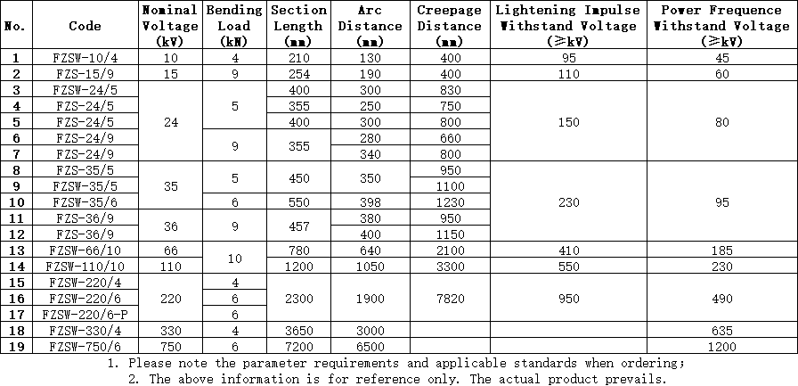
Validation and Testing Methodologies for Cantilever Strength
Theoretical calculations hold no value without physical proof. Elite manufacturers rely on rigorous, transparent testing methodologies. These protocols validate every strength claim before products reach the field.
Type Testing Protocols
Authoritative frameworks dictate baseline cantilever ratings during initial product development. Organizations like IEEE and IEC establish strict parameters. For example, IEC 61952 dictates exactly how engineers apply force and measure failure. Type tests push prototypes to absolute destruction. They confirm the baseline mathematical models used by composite engineers.
The Bending Test Process
Physical load testing demands precision instrumentation. Laboratories execute a specific sequence to validate cantilever strength properly:
- Base Mounting: Technicians bolt the insulator base to a perfectly rigid steel testing frame.
- Force Application: Hydraulic rams apply gradual perpendicular force directly to the top metal fitting.
- Deflection Measurement: Laser sensors record millimeter-by-millimeter bending as pressure increases.
- Acoustic Monitoring: Sensitive microphones listen for internal acoustic emissions. These sounds detect invisible micro-fractures inside the fiberglass matrix.
- Failure Logging: Engineers record the exact force applied when catastrophic failure finally occurs.
Routine Batch Testing
Type tests validate the design, but they do not guarantee daily manufacturing quality. Routine batch testing bridges this gap. Responsible suppliers test a specific percentage of every single production run. These routine checks verify consistent fiberglass reinforced polymer (FRP) core quality. They also validate flange-crimping integrity. Uneven factory crimping easily destroys a perfectly good FRP core.
Application Variances: Horizontal vs. Vertical Load Dynamics
Installation orientation completely changes how an insulator experiences physical stress. Engineers must adjust their load calculations based on the mounting angle.
Vertical Configurations
Substations predominantly utilize vertical layouts. In these setups, the core handles heavy axial compression. The weight of heavy busbars pushes straight down through the center of the fiberglass rod. Cantilever stresses only occur during lateral wind gusts or short-circuit events. Vertical configurations inherently distribute weight more efficiently across the base.
Horizontal Configurations
Wall-mounted components face a much harsher reality. A horizontal line post insulator experiences constant, punishing bending moments. Gravity constantly pulls the heavy conductor downward, perpendicular to the core. Transverse wind loads multiply this downward force. These unique continuous bending stresses require strict safety factor adjustments compared to vertical setups.
Consider these distinct stress profiles:
- Vertical Loads: High axial compression, intermittent lateral stress, lower baseline bending moment.
- Horizontal Loads: Zero axial compression, continuous high bending moment, severe gravitational leverage.
Mounting and Hardware
We must emphasize one critical external factor. The cantilever rating relies entirely on base rigidity. A highly rated product will fail prematurely if the supporting steel structure flexes. Soft mounting brackets absorb and redirect forces unevenly into the brittle core. You must always ensure the mounting structure matches the mechanical rigidity of the insulator itself.
Shortlisting Suppliers: Evaluation Criteria and Risk Mitigation
Procurement teams hold the ultimate responsibility for grid safety. You must aggressively vet supplier claims. Never accept a published SCL rating at face value without seeing hard evidence.
Verifying Claims
Demand comprehensive documentation before signing any purchase order. Buyers must request certified third-party type test reports. Ask for routine test logs from recent production batches. Furthermore, insist on raw material traceability. You need proof regarding the origin of the FRP core and the silicone housing adhesion agents. Low-quality resin matrices degrade rapidly outdoors, silently reducing the MDCL over time.
Avoiding Over-Specification
Engineers often over-specify cantilever loads out of fear. This practice drives up infrastructure budgets unnecessarily. Achieving an artificially high SCL requires thicker FRP cores. Thicker cores drastically increase unit weight and raw material costs. Heavier insulators also demand stronger, more expensive mounting structures. Guide your buyers to match ratings strictly to realistic environmental data and localized fault-current models.
Crimping Technology Assessment
The attachment point between the metal end-fitting and the fiberglass core represents the weakest structural link. Evaluate the manufacturer's crimping process closely. Uneven crimping pressure crushes the fiberglass fibers. This invisible damage becomes the primary cause of premature cantilever failure. Multi-directional acoustic crimping monitors ensure perfectly distributed pressure, preserving the core's theoretical strength.
Table 1: Best Practices vs. Common Mistakes in Supplier Evaluation
| Evaluation Category | Industry Best Practice | Common Procurement Mistake |
| Testing Verification | Demanding third-party IEC/IEEE certified test reports for the exact model. | Accepting internal factory test reports without independent laboratory validation. |
| Load Specification | Calculating loads based on 50-year local wind and ice data models. | Arbitrarily doubling the required SCL "just to be safe" driving up budget. |
| Manufacturing Audit | Inspecting the acoustic emission controls used during the flange crimping process. | Ignoring end-fitting attachment methods and focusing only on silicone thickness. |
Conclusion
Specifying the correct cantilever load remains a foundational pillar of grid reliability. Success requires a deep understanding of the clear division between theoretical limits (SCL) and safe, daily working loads (MDCL). You cannot achieve true infrastructure security without relying on rigorous, standardized physical testing.
We encourage procurement teams to take immediate action. Audit your current high-voltage infrastructure specifications today. Consult your internal engineering teams to determine your actual, localized dynamic load requirements. Finally, always request comprehensive load-deflection curves from shortlisted suppliers before finalizing any purchase. Transparent data prevents catastrophic failures.
FAQ
Q: What is the standard safety factor for a composite post insulator's cantilever load?
A: Most international standards utilize a strict 2:1 safety ratio. The Maximum Design Cantilever Load (MDCL) is set at 50% of the Specified Cantilever Load (SCL). This generous safety margin accounts for long-term material aging, unpredictable extreme weather events, and sudden dynamic electro-mechanical forces.
Q: Does the length or creepage distance of the insulator affect its cantilever strength?
A: Yes, length heavily impacts mechanical strength. Longer units act as larger levers, multiplying the bending force applied to the base. Consequently, longer insulators naturally exhibit lower cantilever strength unless manufacturers significantly increase the internal core diameter to compensate for the added leverage.
Q: How does temperature affect the SCL rating?
A: High-quality FRP cores maintain excellent mechanical stability across standard operating temperatures. However, extreme, prolonged ambient heat can marginally soften the internal resin matrix. This slight softening temporarily reduces overall stiffness, highlighting the need for high-grade epoxy resins in desert environments.
Q: Can a horizontal line post insulator be used in a vertical application?
A: Mechanically, a horizontal unit can handle vertical loads efficiently. However, interchangeability presents electrical problems. Engineers specifically design weather sheds and creepage distances for horizontal water runoff. Using them vertically disrupts optimal self-cleaning properties, heavily compromising long-term electrical performance.


