For utility engineers and procurement teams, specifying a suspension composite insulator represents a high-stakes decision. Underestimating line loads leads directly to catastrophic mechanical failure and extended grid downtime. Unlike traditional porcelain or glass units, modern composite variants rely on a specialized fiberglass core protected by a polymer housing. This fundamental structural difference requires a distinct methodology for mechanical load rating. You cannot simply apply legacy ceramic metrics to flexible composite materials safely. Doing so risks rapid internal degradation and severe safety hazards along transmission lines.
This guide breaks down the technical rating frameworks, compliance standards, and real-world evaluation criteria. You need these exact tools to confidently specify and procure the correct hardware for your transmission project. By mastering these load concepts, you ensure your infrastructure easily withstands extreme weather events and relentless everyday stress.
Key Takeaways
- SML and RTL dictate baseline strength: Specified Mechanical Load (SML) and Routine Test Load (RTL) are the primary metrics used to verify core strength and long-term reliability.
- Application dictates rating type: A high voltage tension insulator requires higher sustained load ratings compared to a standard suspension unit due to constant dead-end stress.
- Voltage scaling alters mechanical needs: Upgrading to an extra high voltage suspension insulator requires factoring in corona ring integration and its impact on the overall load-bearing assembly.
- Standardized testing is non-negotiable: Manufacturer claims must be validated against standardized testing frameworks (e.g., IEC 61109 or ANSI C29.11) to ensure procurement safety.
Decoding the Mechanical Rating Framework: SML and RTL
Understanding mechanical capacities begins by dissecting the core rating framework. Manufacturers quantify strength through specific laboratory metrics. The Specified Mechanical Load (SML) defines the ultimate mechanical strength rating guaranteed by the manufacturer. During type testing, operators apply immense tension to the unit. The insulator must withstand this exact load for one continuous minute. During this critical window, the fiberglass core cannot fail, and the metal end fittings must not pull out. Procurement standards utilize the SML to establish safe operational margins. Best practices dictate sizing your assemblies carefully. Your maximum expected working load should never exceed 50% of the SML.
The Routine Test Load (RTL) serves a different but equally vital purpose. Facilities apply this proof load to every single manufactured unit before clearing it for shipment. Engineers typically set the RTL at 50% of the stated SML. This rigorous quality control step validates the physical crimping process used on the end fittings. It guarantees no latent manufacturing defects compromise the hidden fiberglass core. A properly vetted Suspension Composite Insulator arrives on site already proven against these baseline stresses.
Beyond standard load limits, evaluators must analyze the Mechanical Damage Limit (MDL). Advanced acoustic emission testing determines the MDL during laboratory trials. This test identifies the exact threshold where irreversible micro-cracking begins inside the fiberglass core matrix. Establishing this limit provides a crucial metric for long-term lifecycle planning, ensuring units never experience fatigue loads exceeding this threshold during field operation.
Application Specifics: High Voltage Tension Insulator vs. Suspension Loading
Field application dictates the exact mechanical rating methodology. Vertical suspension loads behave very differently than horizontal tension loads. In a standard suspension configuration, the assembly primarily bears the static weight of the attached conductor, accumulated winter ice, and associated metal hardware. However, static calculations alone fall short. Dynamic environmental factors complicate this baseline. Wind uplift forces and violent galloping conductors demand specific fatigue testing considerations to prevent cyclical wear.
Horizontal tension applications introduce severe, continuous strain. Dead-end towers require hardware capable of holding massive longitudinal forces indefinitely. When you deploy a composite long rod insulator in a tension role, the entire core experiences extreme, unrelenting stress. Evaluators must shift their focus toward long-term material behavior under tension.
To qualify for these demanding roles, a unit requires stringent creep testing. Creep refers to the slow, permanent elongation of materials under constant stress. Laboratory creep evaluations ensure the fiberglass matrix and the crimped metal end fittings remain dimensionally stable. They cannot stretch or slip over a projected 30-to-50-year lifespan. Therefore, specifying a dedicated high voltage tension insulator demands significantly higher baseline SML ratings compared to standard vertical units.
Material Dynamics: Rating the Silicone Rubber Long Rod Insulator
Mechanical ratings depend entirely on the interplay between three distinct material components. First, the Fiberglass Reinforced Plastic (FRP) core acts as the sole load-bearing element. Evaluators focus intensely on the core diameter and the quality of the surrounding resin matrix. A premium resin matrix distributes tensile stress uniformly across millions of individual glass fibers. Poor resin impregnation leaves dry spots, creating internal shear vulnerabilities.
Second, end-fitting crimp technology dictates assembly survival. Manufacturers compress galvanized steel or aluminum fittings directly onto the FRP core using massive hydraulic force. Precision matters here. Technicians utilize acoustic emission sensors during the crimping phase. This real-time monitoring guarantees a permanent, slip-free connection between the metal hardware and the core. Crucially, it stops the compression process before the metal crushes the delicate fiberglass underneath.
Third, we evaluate the protective exterior. A silicone rubber long rod insulator utilizes its polymer housing purely for environmental defense, as the rubber bears zero mechanical line tension. However, its hydrophobic properties prevent surface tracking and devastating electrical arcing. Preventing electrical failure stops localized thermal degradation. If an arc continuously burns the polymer housing, intense heat eventually reaches the FRP core, destroying its mechanical strength entirely.
Scaling Up: Specifying an Extra High Voltage Suspension Insulator
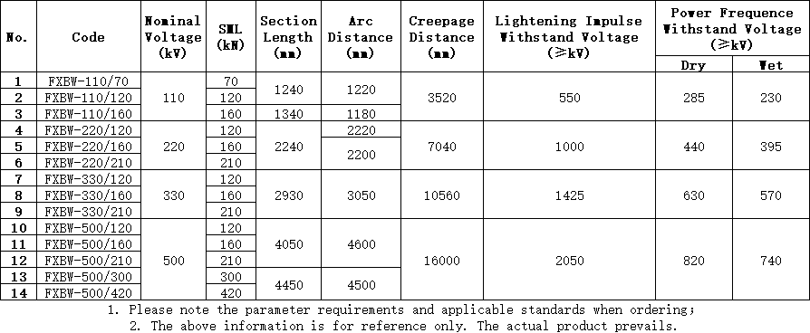
Stepping into extra high voltage (EHV) territories transforms mechanical specifications entirely. High-capacity EHV lines demand massive mechanical ratings, often pushing requirements from 210kN up to 400kN and beyond. Utility planners must calculate the immense weight of multi-bundle conductors utilized in 500kV to 800kV transmission networks. Four-bundle or six-bundle conductor configurations exert tremendous static weight on a single string assembly.
Procuring an extra high voltage suspension insulator introduces mandatory hardware variables. Corona ring integration becomes an absolute necessity at these voltage levels. Adding these metallic rings impacts mechanical hardware connections. They alter the overall string length, changing the mechanical swing dynamics of the tower under high crosswinds.
Furthermore, EHV applications create dangerous overlaps between electric field stress and mechanical stress. The triple point represents the exact location where air, metal hardware, and the polymer housing intersect. We evaluate strict design rules regulating voltage gradients here. Uncontrolled corona discharge will slowly erode the polymer housing near this junction. Over time, moisture breaches the core interface, compromising the mechanical integrity of the entire tower support structure.
Procurement Checklist: Validating Manufacturer Ratings
Do not accept manufacturer load claims without rigorous independent validation. Global utility standards provide clear frameworks for vetting products. Insist on viewing complete, certified Type Test reports. For composite suspension and tension assemblies, IEC 61109 stands as the definitive international standard. In North American markets, ANSI C29.11 provides the equivalent rigorous benchmarks.
You must dive deeply into accelerated aging data before finalizing vendor selections. Evaluate both 1,000-hour and 5,000-hour tracking and erosion test results. These tests simulate decades of harsh environmental exposure. Thermo-mechanical testing data proves equally critical. This specialized testing cycles heavy mechanical loads while rapidly fluctuating temperatures between extreme hot and freezing cold conditions, verifying crimp stability.
Standardized Mechanical Verification Metrics
| Test Category | Primary Metric Assessed | Standard Reference | Pass/Fail Criteria |
| Specified Mechanical Load (SML) | Ultimate tensile strength limit | IEC 61109 / ANSI C29.11 | Hold max load for 1 min without failure |
| Routine Test Load (RTL) | Crimp integrity & core defects | IEC 61109 | Hold 50% SML during factory production |
| Thermo-mechanical Cycling | Hardware stability under temperature extremes | IEC 61109 | No core slippage or housing separation |
| Damage Limit (MDL) Evaluation | Micro-cracking threshold via acoustic emission | CIGRE / IEC TR | Acoustic spikes remain below defined baseline |
To ensure consistent quality, mandate total vendor transparency. Implement the following verification steps into your procurement workflow:
- Request comprehensive factory acceptance testing (FAT) protocols before production begins.
- Demand documented, unit-specific RTL records corresponding to your exact production batch.
- Review the supplier's raw material sourcing, specifically focusing on fiberglass resin suppliers.
- Audit the acoustic emission data logs generated during the end-fitting crimping process.
Implementation Realities: Avoiding Rating Degradation in the Field
Even perfectly rated hardware will fail if mishandled during installation. Field realities often degrade pristine factory ratings. Torsion vulnerability represents the most common hazard. Composite designs boast incredible tensile strength but remain highly susceptible to torsional, or twisting, damage. Twisting a unit to align hardware fractures the internal fiberglass strands instantly, plummeting its actual SML.
Handling and rigging practices present severe operational risks. Crews must adhere to strict installation protocols. Using insulators as steps or bending the core beyond its elastic limit destroys structural integrity. Scraping the silicone housing against steel tower members during lifting invites moisture ingress and eventual electrical tracking.
Finally, we must address hardware compatibility. Ensure clevis-to-tongue or ball-to-socket end fittings perfectly match your existing tower hardware. Mismatched or incorrectly sized pins prevent free articulation. This stiffness causes unequal load distribution. Localized stress concentrations will subsequently shear the metal fitting long before the fiberglass core ever reaches its rated failure point.
Conclusion
Specifying the correct composite insulator demands rigorous adherence to mechanical rating protocols. You must accurately verify SML and RTL limits, ensuring everyday line stress remains well below manufacturer thresholds. Matching the rating type directly to the application proves vital; tension applications require specialized core designs compared to standard vertical setups. Demand strict compliance with IEC or ANSI testing frameworks to eliminate procurement risks.
We recommend cross-referencing your regional environmental factors against these mechanical capacities before finalizing any shortlists. Heavy ice accumulation zones and high-wind corridors require extra safety margins. By combining accurate load data, verified factory testing, and strict field installation protocols, you guarantee long-term grid reliability and prevent catastrophic mechanical drops.
FAQ
Q: What is the difference between SML and working load in composite insulators?
A: SML represents the ultimate failure rating guaranteed by the manufacturer under controlled testing. The maximum working load refers to the everyday sustained stress applied by the conductor. Utility standards dictate everyday working loads should typically not exceed 50% of the SML to ensure a safe 30+ year lifespan.
Q: Can a composite long rod insulator be used for tension dead-end applications?
A: Yes, but it must be specifically rated and tested as a high voltage tension insulator. These applications generate continuous longitudinal strain. Tension units require higher baseline SML ratings and rigorous creep testing to prevent the core or crimped fittings from elongating over decades of service.
Q: How does temperature affect the mechanical rating of a silicone rubber long rod insulator?
A: Temperature fluctuations cause materials to expand and contract. Standard ratings are verified through thermo-mechanical testing. This testing ensures the metal end fittings and the fiberglass core change size at manageable rates, preventing core slippage or crimp failure under extreme weather cycling.
Q: What happens if a composite insulator is subjected to torsional stress?
A: The internal fiberglass core can suffer immediate micro-fractures. Because composite units are designed for longitudinal tension, twisting forces severely compromise the core matrix. This damage significantly reduces the unit's SML, leading to premature line drops. Precise, twist-free installation handling is absolutely required.


