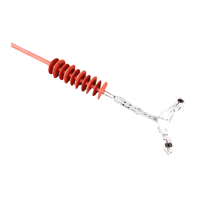
Overhead transmission networks face relentless environmental threats. Few are as destructive as conductor galloping. Picture a sub-zero night in a remote valley. Freezing rain coats the aluminum conductors. Relentless crosswinds follow immediately. These harsh winter conditions trigger massive, low-frequency oscillations across transmission spans. When conductors swing out of control, phase-to-phase flashovers occur. This causes immediate tripped breakers and catastrophic power outages. Beyond the immediate electrical faults, this violent kinetic energy leads to severe hardware fatigue. It degrades insulators and threatens the structural integrity of the towers themselves.
To mitigate these severe risks, utility engineers rely on a structurally sound, mechanically robust intervention. By physically restricting dynamic motion, grid operators maintain critical phase clearances even in the most vulnerable corridors. Specifically, deploying a specialized 220kV Interphase Spacer with Spacer Clamps provides the exact balance of electrical insulation and mechanical grip required to stabilize high-voltage infrastructure. This guide explores the aerodynamic mechanics of galloping, composite spacer engineering principles, and the technical specifications required to ensure grid reliability during extreme weather.
Key Takeaways
Galloping Mitigation: Interphase spacers act as rigid struts that physically restrict the amplitude of conductor oscillations, significantly reducing the risk of phase-to-phase electrical flashovers.
Material Superiority: Modern utility designs rely on lightweight, high-strength fiberglass reinforced polymer cores protected by weather-resistant, hydrophobic silicone rubber sheds.
Targeted Applications: High-voltage corridors require specialized dimensional engineering to meet stringent dry and wet arcing distances without compromising mechanical flexibility.
Clamp Design Matters: The integration of high-quality, articulated spacer clamps is critical to distribute mechanical stress evenly and prevent abrasion to the conductor strands during dynamic movement.
Cost-Efficiency: Installing these composite insulators serves as a highly cost-effective retrofit when compared to the massive capital required for repairing structural tower damage or enduring extended network downtime.
The Destructive Mechanics of Transmission Line Galloping
Transmission line galloping is not a random occurrence. It is a complex aerodynamic phenomenon governed by the Den Hartog criterion of torsional instability. During freezing rain or sleet, ice accumulates asymmetrically on the windward side of the cylindrical conductor. This alters the physical profile of the cable. It transforms into an irregular, D-shaped airfoil. Steady crosswinds striking this newly iced profile generate powerful aerodynamic lift and drag forces.
Unlike aeolian vibration, which manifests as a high-frequency flutter, galloping features low-frequency standing waves ranging from 0.1 to 3 Hz. The amplitude is extraordinarily high. Depending on the span length and line tension, vertical displacements can exceed 10 meters. Metric tons of aluminum and ice swing wildly out of their designated spatial envelopes.
The physical and financial consequences of uncontrolled galloping are multifaceted and severe. As conductors swing out of phase, they breach the minimum required electrical clearance. This results in high-voltage phase-to-phase flashovers. High-energy short circuits trip substation circuit breakers. Widespread power outages follow. The thermal damage to conductor strands is often irreversible.
Furthermore, the mechanical toll on the infrastructure is equally devastating. Massive kinetic energy transfers directly to the attachment points. Insulator strings suffer extreme wear. Crossarms experience bending fatigue. In the worst-case scenarios, repetitive dynamic loading loosens structural bolts. Complete tower collapse or conductor snapping becomes a real threat.
What is an Interphase Spacer?
An interphase spacer is a highly specialized, heavy-duty composite insulator. Line crews install it directly between phase conductors within a transmission span. Standard bundle spacers merely keep sub-conductors of the same phase apart. These devices, however, bridge entirely different phases operating at different potentials.
They serve a critical dual function. Mechanically, they act as a rigid strut. They physically lock the distance between phases, preventing clashes regardless of wind severity. Electrically, they function as high-voltage insulators. Engineers design them with sufficient creepage and arcing distance to prevent surface tracking and short circuits between energized lines.
Historically, utilities attempted to control wind-induced motion using aerodynamic drag dampers or detuning pendulums. These devices alter the torsional characteristics of the line. Their effectiveness remains highly dependent on specific wind speeds and ice shapes. They do not offer a guaranteed physical barrier against heavy, asymmetrical ice loads.
In contrast, the modern interphase spacer represents the ultimate structural fail-safe. By enforcing strict geometric separation, it links the phases together. The conductors are forced to move in unison rather than in opposing waves. This physical coupling fundamentally alters the resonant frequency of the span. It effectively detunes the line and disrupts the formation of galloping waves.
Key Engineering Principles of Interphase Spacer Design
The structural backbone of a modern spacer is its internal fiberglass reinforced polymer rod. Manufactured through a precise pultrusion process using boron-free ECR glass fibers and epoxy resin, the core delivers exceptional tensile and compressive strength. During a violent galloping event, the spacer must withstand immense compressive buckling forces as the phases attempt to crash together. Sudden tensile shock loads immediately follow as the ice sheds and the cables rebound.
Engineers calculate the exact diameter and composition of the fiberglass rod. It must possess enough rigidity to maintain phase separation, yet retain a calculated degree of flexibility. This flexibility allows the rod to absorb and dissipate a portion of the kinetic energy. It prevents the rigid transfer of shockwaves directly into the conductor clamps.
Because the spacer connects two live phases, its exterior must provide flawless electrical isolation. The core is encapsulated in a High-Temperature Vulcanized silicone rubber housing, molded into aerodynamic sheds. Silicone rubber offers superior hydrophobicity. In wet and freezing conditions, water beads up and rolls off the sheds. This prevents the formation of a continuous conductive water film.
The polymer formulation must offer excellent resistance to ultraviolet degradation, ozone exposure, and electrical surface tracking. The aerodynamic profile and alternating diameters of the sheds are mathematically optimized. This maximizes the surface creepage distance, ensuring reliable performance over a decades-long lifespan.
Feature
Traditional Dampers
Composite Interphase Spacers
Primary Mechanism
Alters torsional line characteristics
Physically locks phase distance
Effectiveness on Heavy Ice
Low to Moderate
Extremely High
Electrical Function
None required
Acts as a high-voltage insulator
Installation Location
Single phase attachment
Bridges multiple live phases
Deep Dive: The 220kV Interphase Spacer with Spacer Clamps
Standard off-the-shelf solutions frequently fall short in high-voltage transmission networks. Engineering parameters require rigorous calculation to handle extreme electrical gradients and heavier conductor bundles. In a 220kV network, minimum dry and wet arcing distances must be strictly maintained. The length of the spacer is dictated by the maximum switching overvoltages and lightning impulse withstand requirements of the system.
For 220kV applications, the section length of the composite insulator typically ranges from 2000 mm to 2500 mm. The specific creepage distance is tailored to the pollution severity level of the site. Utilizing high-voltage interphase spacer solutions ensures electrical integrity remains uncompromised, even under heavy rain or coastal salt fog.
The insulator body is only as reliable as its connection to the line. The spacer clamp serves as the critical interface. Here, dynamic mechanical stress transfers from the rigid rod to the flexible aluminum conductor. Poorly designed clamps create stress concentrations. This causes bending fatigue in the rod or abrasive wear on the conductor strands.
High-quality 220kV assemblies utilize articulated spacer clamps rather than strictly rigid joints. These clamps feature hinge mechanisms allowing multi-directional rotational movement. When the conductor vibrates, the articulated joint pivots. It safely absorbs kinetic energy without transferring destructive bending moments. Premium clamps often integrate specialized elastomers or armor rods. This distributes the compressive grip force over a larger surface area, providing a secure, non-abrasive grip.
Industry Trends in Transmission Corridor Resilience
A broader look at the global energy sector reveals a distinct shift toward proactive climate adaptation. As meteorological patterns grow increasingly erratic, grid operators are prioritizing mechanical hardening over traditional redundancy. We are seeing a surging demand for composite insulators capable of withstanding both severe pollution and extreme dynamic loading without requiring frequent maintenance.
The market is witnessing a trend toward customized specific creepage distances tailored to micro-climates. The one-size-fits-all approach is obsolete. Modern utilities align with the mandate for predictive grid reliability and sustainable infrastructure management. Smart grid integration is also emerging. Future spacers may incorporate sensor technology to monitor line tension and galloping frequency in real-time. This data-driven approach allows utilities to predict fatigue life and schedule targeted maintenance before structural failures occur.
Actionable Selection Guide for Network Engineers
For procurement managers and utility engineers, selecting the appropriate vendor requires strict adherence to quality assurance standards. Instead of abstract concepts, field engineers rely on a concrete checklist when sourcing hardware.
First, verify the Specified Mechanical Load rating. For a 220kV system experiencing heavy ice loads, the spacer must exhibit a high compressive and tensile failing load. This often exceeds 100kN depending on span length and conductor bundle weight.
Second, evaluate the clamping mechanism. Ensure the manufacturer provides articulated clamps compatible with your specific conductor diameter. Rigid clamps will inevitably cause strand fatigue under severe galloping conditions.
Third, review the electrical type tests. The hardware must pass rigorous dry and wet power-frequency voltage tests. Partnering with an experienced manufacturer ensures you receive custom-engineered 220kV interphase spacers built to survive both the structural mechanics and the high-voltage electrical environments specific to your corridor.
Best Practices for Installation in Galloping-Prone Corridors
Procuring the right hardware is only the first step. Correct installation geometry is vital. A common misconception is that a single spacer should sit in the exact dead-center of a transmission span. Galloping often occurs in multiple harmonic modes, such as two-loop or three-loop waves. Placing a spacer exactly in the middle might inadvertently create a stationary node for a higher-order harmonic. This fails to stop the motion.
Transmission line designers utilize simulation software to determine optimal, asymmetric placement. Crews typically install spacers at one-third and two-thirds span intervals. This asymmetrical positioning effectively disrupts multiple modes of oscillation simultaneously. Harmonic waves cannot build continuous momentum.
One of the greatest advantages of this technology is its viability as a retrofit solution. Upgrading a galloping-prone corridor does not require the massive capital expenditure of reconductoring the line or rebuilding transmission towers. Installing spacers is a highly targeted, localized intervention. Using specialized insulated tools and bucket trucks, trained linemen perform the installation using live-line working techniques like hot-stick or bare-hand methods. The utility proactively secures the corridor against winter weather without interrupting power delivery.
Conclusion
Severe winter weather continues to threaten modern power grids. Robust motion control is a critical necessity. As ice and wind combine to turn passive cables into destructive forces, relying on outdated mitigation methods is no longer viable. Implementing strict physical separation through composite insulator technology is the most proven method to prevent phase-to-phase clashing.
Investing in quality infrastructure is a proactive strategy. It saves utilities millions in emergency repair costs and network downtime. Secure your transmission corridors and maintain flawless power delivery by exploring premium interphase spacers and transmission hardware tailored to your specific environmental challenges.
Frequently Asked Questions
How does an interphase spacer differ from a standard bundle spacer?
A bundle spacer is designed to keep sub-conductors of the same phase apart to prevent electromagnetic attraction and clashing. In contrast, an interphase spacer is a heavy-duty composite insulator installed between entirely different phases. Its primary role is to prevent these live phases from clashing and causing short circuits during severe galloping events.
Can interphase spacers completely eliminate transmission line galloping?
While no device can stop the aerodynamic interaction between the wind, ice, and the conductor, interphase spacers effectively restrict the amplitude of the movement. By physically tying the phases together, they prevent the conductors from getting close enough to breach electrical clearances and cause a flashover.
How many interphase spacers are required per span?
The exact number depends on the span length, conductor tension, and historical galloping data of the specific corridor. Typically, engineers specify one to three spacers per span. They are strategically placed at specific asymmetrical intervals to efficiently break up complex oscillation waves.
Why is the spacer clamp design so vital for a 220kV Interphase Spacer?
The clamp serves as the critical physical interface between the rigid spacer rod and the dynamic aluminum conductor. A poorly designed, rigid clamp can cause severe friction and bending stress, leading to conductor strand breakage over time. High-quality spacer clamps feature articulated joints and protective elastomer grips to safely absorb and transfer kinetic energy without damaging the line.
What is the expected lifespan of a composite interphase spacer?
When manufactured with premium high-temperature vulcanized silicone rubber, boron-free ECR glass fiber cores, and hot-dip galvanized corrosion-resistant hardware, composite interphase spacers are highly durable. They can reliably serve on a transmission line for twenty to thirty years, even when subjected to harsh, galloping-prone environments and high ultraviolet exposure.
How do engineers calculate the correct placement of interphase spacers?
Engineers use advanced computational fluid dynamics and finite element analysis software to model the specific span. By simulating wind loads and ice accumulation, they identify the resonant frequencies and harmonic nodes of the line. Spacers are then placed asymmetrically to disrupt these specific wave formations.
Can interphase spacers be installed on energized lines?
Yes. Trained utility crews frequently install interphase spacers on live lines using specialized live-line working techniques. Utilizing insulated hot-sticks or bare-hand methods from insulated bucket trucks allows the utility to retrofit vulnerable corridors without requiring costly power outages.