Upgrading utility infrastructure for narrow right-of-ways often requires transitioning from crossarms to horizontal orientations. However, horizontal installations shift the mechanical stress entirely. They move the primary forces from standard compression to cantilever loads. This fundamental change alters how engineers must design and align overhead systems.
Incorrect alignment compromises vital clearances. It leads to water bridging across weather sheds during storms. Furthermore, it drastically increases the risk of mechanical failure under heavy ice or high wind loads. Field crews frequently face challenges adjusting these setups correctly on wood or steel poles. A minor angular deviation at the pole face magnifies into significant conductor sag at the tip.
This article provides an engineering-focused evaluation of horizontal alignment principles. We aim to help utility buyers, project engineers, and procurement teams specify and install the correct components. You will learn how to manage cantilever stress, evaluate weather shed geometry, select proper end fittings, and navigate regulatory clearance standards.
Key Takeaways
- Proper alignment converts conductor weight into a predictable cantilever bending moment; failing to match insulator base curvature to pole diameter causes premature base failure.
- Weather sheds must be oriented correctly relative to the ground (often prompting the "is it installed backwards?" field question) to maintain dry banding and prevent flashovers.
- Regulatory baselines (such as CPUC GO 95 Rule 54.11) dictate minimum phase-to-pole clearances that directly influence base-to-end alignment requirements.
- Selection of the top fitting dictates the final alignment tolerance and limits conductor vibration wear.
The Mechanical Case for Precise Horizontal Alignment
Unlike vertical configurations, horizontal mounting subjects the core to constant cantilever bending forces. Gravity pulls the conductor downward at the tip. This creates a severe lever effect against the base. Engineers define the maximum design cantilever load (MDCL) to quantify this stress. You must select a robust Horizontal Line Post Insulator rated specifically for these extreme bending moments. The internal fiberglass rod acts as the primary structural spine. It resists transverse loads from wind and vertical loads from ice simultaneously.
Base-to-pole integration determines the long-term survival of the installation. Evaluate how the base casting aligns flush with the pole face. You will find distinct differences between flat-base installations and curved-base installations. Flat bases suit square structures like lattice towers or square concrete poles. Conversely, curved bases wrap around round wood, concrete, or tubular steel poles. Using a flat base on a round pole creates point loading. This misalignment concentrates stress on the mounting bolts and causes premature hardware failure.
Acceptable deflection under load represents a critical safety metric. A standard line post insulator will bend slightly under normal operational loads. However, severe misalignment exaggerates line sag significantly. As the tip droops lower than intended, it compromises required phase spacing. Engineers must consult the manufacturer’s deflection curves during the design phase. You need to verify the tip will not sag beyond safety thresholds when subjected to maximum ice accumulation.
Weather Shed Orientation: Avoiding the "Backwards" Installation Trap
Alternating shed designs maximize creepage distance while preventing continuous water trails. Geometry dictates electrical performance in wet conditions. When installing a horizontal composite post insulator, the angle of the sheds must correctly face downward toward the earth. This downward angle forces rain to drip off the edges. It maintains dry bands beneath the sheds. Dry bands interrupt leakage currents and prevent dangerous flashovers across the polymer housing.
A perfectly 90-degree horizontal alignment rarely occurs in utility practice. Most standard installations require a 5-degree upsweep. You tilt the base upward slightly during installation. This upsweep compensates for the inevitable downward pull of the conductor weight. Once you attach the heavy cable, the unit settles closer to true horizontal. More importantly, this slight upward tilt ensures proper moisture run-off. If you mount it perfectly flat initially, conductor weight drags it into a negative angle. Water will then pool near the core.
Field inspectors need reliable visual diagnostics to identify incorrectly aligned units. Crews often ask if a unit is installed "backwards." Use these criteria to evaluate field installations quickly:
- Shed Taper Direction: The wider section of the shed taper should face away from the pole when mounted horizontally.
- Drip Edge Position: Drip edges must point downward toward the ground. Upward-pointing edges collect debris.
- Water Pooling: Check for standing water on the "top" of the sheds after rain. This reduces effective creepage distance.
- Dirt Accumulation: Look for abnormal dirt banding on surfaces intended to self-clean during rainfall.
Conductor Attachment Alignment: Tie Top vs. Clamp Top Systems
Evaluating the alignment requirements for a tie top line post insulator reveals strict neck tolerances. The insulator neck must perfectly align parallel to the conductor path. Field crews use binding wires to secure the conductor into the top groove. If the alignment is off-axis, the binding wires cannot seat correctly. This creates localized stress points. Over time, these friction points dig into the aluminum strands and damage the conductor jacket.
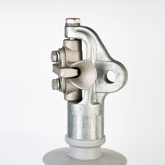
Clamp top systems utilize trunnion or drop-tongue mechanisms to secure the line. Compare horizontal and vertical trunnion orientations based on your specific line angles. A vertical trunnion clamp allows slight vertical articulation. A horizontal trunnion clamp allows horizontal sweep. The clamp aligns the conductor smoothly to minimize torsional stress on the fiberglass core. Twisting forces degrade the polymer-to-rod seal. Proper clamp alignment keeps the load strictly in the cantilever plane.
Micro-misalignments at the attachment point lead to severe wear over decades. Conductor chafing happens when wind induces aeolian vibrations. The metal rubs against the clamp or tie wire repeatedly. This friction generates radio interference voltage (RIV) issues. RIV creates static on local communication lines. It also signals active corona discharge. Corona discharge slowly degrades the polymer housing material around the end fitting.
Top Fitting Alignment Comparison
| Fitting Type | Alignment Tolerance | Torsional Stress Risk | Vibration Wear Risk | Ideal Application |
| Tie Top | Low (Must be perfectly on-axis) | Moderate | High (If ties loosen) | Lower voltage, smaller conductors |
| Vertical Trunnion | Moderate (Allows vertical pivot) | Low | Low | Heavy ice load zones |
| Horizontal Trunnion | Moderate (Allows lateral pivot) | Low | Low | Line angles and gentle curves |
| Drop-Tongue | High (Suspends the clamp) | Very Low | Low | High voltage, large conductors |
Clearance Standards, Right-of-Way, and Regulatory Compliance
Horizontal alignment maximizes the physical distance from the pole center. This configuration pushes the live phase straight out into the air space. It removes the necessity for wide wooden crossarms. You achieve excellent phase-to-ground spacing while keeping the pole profile remarkably slim. Engineers rely on this geometry to thread transmission lines through congested areas safely.
Regulatory baselines establish strict evaluation criteria for horizontal clearance. You must reference standard frameworks such as CPUC GO 95 Rule 54.11 or the National Electrical Safety Code (NESC). These codes dictate absolute minimum phase-to-pole clearances. They account for linemen climbing the structure and extreme weather deflection. Base-to-end alignment requirements directly influence these measurements. A unit sagging just three degrees past specification might violate the legal clearance limit during a summer thermal event.
Framing the business case for horizontal configurations centers on right-of-way (ROW) optimization. Urban corridors offer highly restricted real estate. Land acquisition costs prohibit widening the utility corridor. Exact horizontal alignment allows utilities to increase voltage classes within these same restricted footprints. You can upgrade a 69kV line to 115kV on the existing poles. The compact horizontal profile keeps the higher voltage phases safely within the existing legal boundaries.
Special Applications: Aligning Equipment Supports
Evaluate the alignment logic differently when the unit is not holding a transmission line. Utilities frequently use horizontal configurations to support ancillary equipment. Examples include voltage regulators, switchgear, and capacitor banks. These applications require rigid standoffs. The base must resist both the dead weight of the equipment and wind loading against the equipment's surface area. Alignment errors here cause the mounted equipment to hang out of plumb.
Dynamic shock loads introduce unique alignment challenges. When evaluating a fuse cutout support insulator, alignment must account for sudden physical violence. A fuse operating under a fault condition generates a strong directional shock. The mechanism kicks back forcefully. The support must possess high torsional resistance to handle this physical blow. If the mounting bolts are misaligned, this repeated shock load will gradually tear the base hardware out of the wood pole.
Bracket phasing requires precise evaluation dimensions. Utilities often mount multiple units on a single multi-phase standoff bracket. You must align all three phases perfectly parallel. A slight rotational twist in the main bracket alters the entire phase geometry. Staggered alignments sometimes help prevent flashovers between adjacent equipment drops. Engineers must ensure the mounting bracket integrates cleanly with the pole face to maintain spacing integrity.
Implementation Risks and Procurement Evaluation Checklist
Adoption risk remains a factor when crews transition between materials. Polymer and porcelain handle mechanical stress very differently. Porcelain is rigid and unforgiving. Polymer flexes visibly under heavy load. Alignment torque specifications must match the specific material. If field crews overtighten the mounting bolts on a polymer unit, they risk crushing the internal fiberglass rod. If they under-tighten porcelain, the brittle base might crack under vibration.
Ensure hardware compatibility during the procurement phase. The mounting bolts, gain plates, and backing washers must match the pole type exactly. Gain plates provide a secure flat mating surface on round wood poles. Backing washers distribute the immense clamping force across the wood grain on the opposite side. Wood poles experience shrinkage as they dry over time. You must specify spring washers to prevent alignment shifting due to this natural pole shrinkage.
Apply a strict shortlisting logic before approving components. Use this evaluation sequence:
- Verify the required creepage distance based on local pollution levels.
- Select the correct base style (gain for round poles, flat for square structures).
- Choose the appropriate end fitting (tie, clamp, or equipment bracket).
- Match the specified MDCL directly to the environmental load expectations for wind and ice.
Conclusion
The correct alignment of a horizontal system is not merely a reactive field installation task. It begins proactively at the procurement stage. You must match the base curvature, shed orientation, and cantilever strength precisely to the specific pole and environment. Ignoring these factors leads to structural failure, regulatory violations, and costly unplanned outages. The internal rod relies entirely on a stable, flush mounting surface to resist bending forces effectively.
Advise utility engineers to cross-reference their local clearance regulations carefully before ordering. Compare frameworks like the NESC or GO 95 directly against the manufacturer’s cantilever deflection curves. Always finalize these mechanical calculations before approving the Bill of Materials (BOM). Procuring the exact base hardware and end fittings ensures field crews can achieve perfect horizontal alignment on the first attempt.
FAQ
Q: Can a standard line post insulator be installed horizontally?
A: Only if specifically rated for horizontal cantilever loads. Standard vertical insulators are primarily designed for compression and tensile loads. They lack the core strength for lateral bending and will fail if misapplied horizontally. Always verify the Maximum Design Cantilever Load (MDCL) rating before horizontal installation.
Q: What is the standard mounting angle for horizontal insulators?
A: Most manufacturers recommend a 5-degree upward tilt (upsweep) rather than a true 0-degree horizontal alignment. This slight upward angle compensates for immediate conductor deflection under weight. It also aids in water shedding, ensuring rain flows away from the core to maintain dry bands.
Q: How do you know if a horizontal composite insulator is installed backwards?
A: The weather sheds are designed to shed water downward. If the wider part of the shed taper is facing the pole and trapping water against the core, or if the drip edges point upward, it is installed incorrectly. This error will likely cause tracking or flashovers.
Q: Do horizontal installations require different mounting hardware?
A: Yes. Because of the extreme bending moment, horizontal installations typically require specialized curved bases, longer through-bolts, and large backing plates. These components distribute the intense leverage force across the pole structure and prevent the mounting bolts from pulling through the wood or steel.


